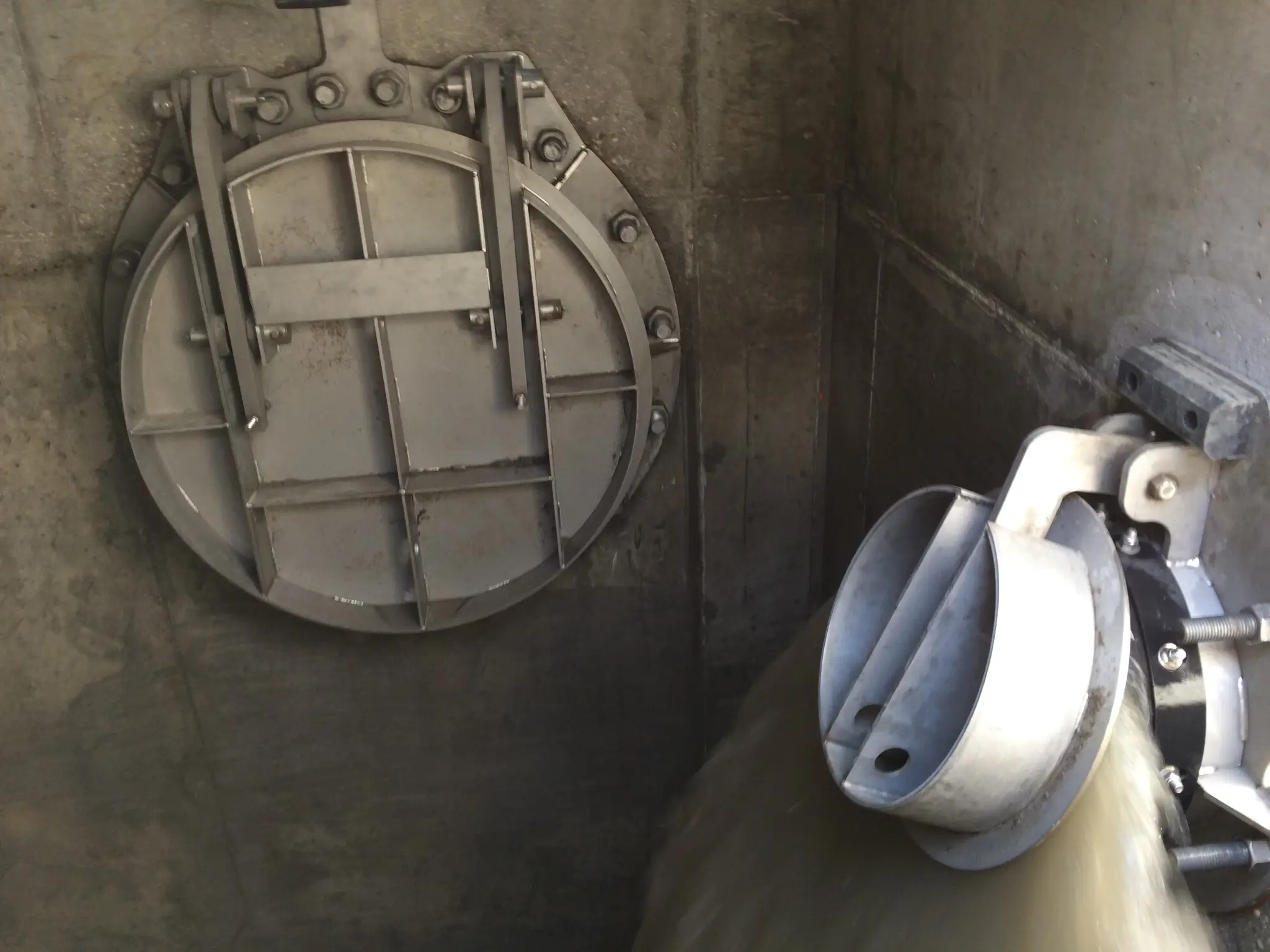
Flap Gates
Prevent backflow in drainage systems automatically, ensuring reliable, one-way flow.
Technical specifications
General
- The flap gates for this project shall be provided as specified and as shown in the Contract Documents.
Performance Requirements
- Leakage for the flap gates shall be restricted to 0.1 gpm/ft or less of the seal perimeter at the design seating head.
Submittals
- Submittals shall include, at a minimum, detailed custom drawings of the gate assembly with dimensional and mounting information and a listing of the materials of construction. General arrangement drawings and cut sheets are not considered acceptable drawings.
- A copy of the ISO 9001:2015 certification.
Quality Assurance
- The basis for the design of the flap gates is the Model RW5000-A as manufactured by RW Gate Company, Troy, NY.
- All gates shall be shop inspected for proper operation prior to shipment.
- Welds shall be performed by welders with ASME Section IX or AWS D1.2 certification.
- The gate manufacturer shall be ISO 9001:2015 certified.
Materials of Construction
- All aluminum referenced in this specification shall be alloy 6061-T6, ASTM B308/308M.
- All stainless steel referenced in this specification shall be Type 304 or Type 304L, ASTM A240 or ASTM A276 unless otherwise indicated herein.
- All non-welded stainless steel components, excluding anchor bolts and assembly bolts, shall be Type 304 or Type 304L stainless steel.
- Anchor bolts and assembly bolts shall be Type 316 stainless steel.
Flap
- The flap shall consist of an aluminum plate that is reinforced with stiffeners to withstand the specified head conditions.
- The flap shall be reinforced with plates or channel shaped members to restrict deflection to 1/16-inch or less at the design head.
- The stiffeners shall be welded to the flap.
- A lifting lug shall be provided on the lower portion of the flap.
Frame
- The frame shall be constructed of aluminum and shall be reinforced to withstand the specified operating conditions.
- The frame shall be a rigid, one-piece assembly of the configuration shown on the Contract Documents.
- The frame shall be outfitted with a resilient seal around the perimeter of the opening.
- Aluminum hinge arms shall connect the flap to the frame.
- Hinge bushings shall be UHMWPE or bronze.
Seals
- The seal shall consist of a continuous rubber lip seal mounted around the perimeter of the opening.
- J-bulb seals, P-seals and D-seals are not acceptable in lieu of lip-type seals.
- All seals shall be secured with assembly bolts. All seals shall be field removable and field replaceable without the need to remove the gate frame from the wall.
Anchorage
- Anchor bolts for the gate assembly and appurtenances shall be provided by the gate manufacturer.
- The anchor bolts shall be 316 stainless steel, fully threaded and shall have a minimum diameter of 1/2-inch.
- Anchor bolts shall be of the epoxy type.
Finish
- All aluminum shall be mill finish.
- Aluminum in contact with concrete shall be field coated by the Contractor.
Installation
- Installation shall be performed in accordance with the gate manufacturer's installation instructions and the approved installation drawings.
- Installation instructions and installation drawings shall be found in the O&M manual.
- Non-shrink grout or a resilient gasket shall be applied, by the Contractor, between the frame and the wall to ensure that there is no leakage around the gate.