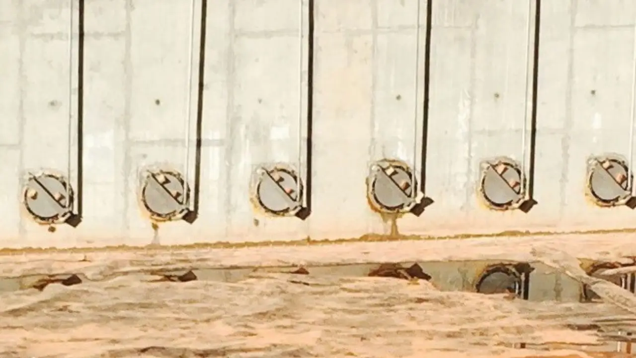
Shear Gates
Designed for fast operation and secure water cutoff in high-flow channels.
Technical specifications
General
- The hand-pull shear gates shall be provided as specified and as shown in the Contract Documents.
Performance Requirements
- Leakage for the shear gates shall be restricted to 0.1 gpm/ft or less of the seal perimeter at the design seating head and unseating head.
- Shear gates shall be designed to be suitable for the application and designed to handle 10-ft of seating head and 10-ft of unseating head as a minimum.
Submittals
- Submittals shall include, at a minimum, detailed custom drawings of the gate assembly with dimensional and mounting information and a listing of the materials of construction. General arrangement drawings and cut sheets are not considered acceptable drawings.
- A copy of the ISO 9001:2015 certification.
Quality Assurance
- The basis for the design of the shear gates is the Model RW7400-S as manufactured by RW Gate Company, Troy, NY.
- All gates shall be shop inspected for proper operation prior to shipment.
- Welds shall be performed by welders with ASME Section IX certification.
- The gate manufacturer shall be ISO 9001:2015 certified.
Materials of Construction
- All stainless steel referenced in this specification shall be Type 304 or Type 304L, ASTM A240 or ASTM A276 unless otherwise indicated herein.
- All welded stainless steel components shall be constructed of Type 304L stainless steel.
- All structural stainless steel used in the construction of slide plates and frames shall have a minimum material thickness of 3/16-inch.
- All non-welded stainless steel components, excluding anchor bolts and assembly bolts, shall be Type 304 or Type 304L stainless steel.
- Anchor bolts and assembly bolts shall be Type 316 stainless steel.
Slide Plate
- The slide plate shall consist of a stainless steel plate that is formed and reinforced as necessary to withstand the specified head conditions.
- The slide plate shall be provided with a connection point for the lifting handle.
- Lifting handles shall be formed from round bar or shall be lifting slots in the top of the stop plate as shown on the Contract Drawings.
Frame
- The frame shall be constructed of stainless steel plate, formed as necessary for rigidity, and shall be reinforced to withstand the specified operating conditions.
- The frame shall be a rigid, one-piece assembly.
- The frame shall be of the configuration as shown in the Contract Drawings.
- A resilient seal shall be provided on the frame and the seal shall be secured with assembly bolts.
- All seals shall be field replaceable without the need to remove the frame from the wall.
Lifting Handle
- The lifting handle shall have a T shape and shall be constructed of 1-inch minimum diameter stainless steel tube.
- A stainless steel mounting bracket shall be provided to secure the lifting handle.
- An adjustable hook shall be provided as part of the lifting handle assembly to hold the slide plate at defined travel positions.
Anchorage
- Anchor bolts for the gate assembly and appurtenances shall be provided by the gate manufacturer.
- The anchor bolts shall be 316 stainless steel, fully threaded and shall have a minimum diameter of 1/2-inch.
- Anchor bolts shall be of the epoxy type.
Finish
- All heat tint and slag from the welding process shall be passivated in accordance with ASTM A380.
Installation
- Installation shall be performed in accordance with the gate manufacturer's installation instructions and the approved installation drawings.
- Installation instructions and installation drawings shall be found in the O&M manual.
- A resilient gasket and/or mastic shall be applied, by the Contractor, between the frame and the pipe flange or wall to ensure that there is no leakage around the gate.