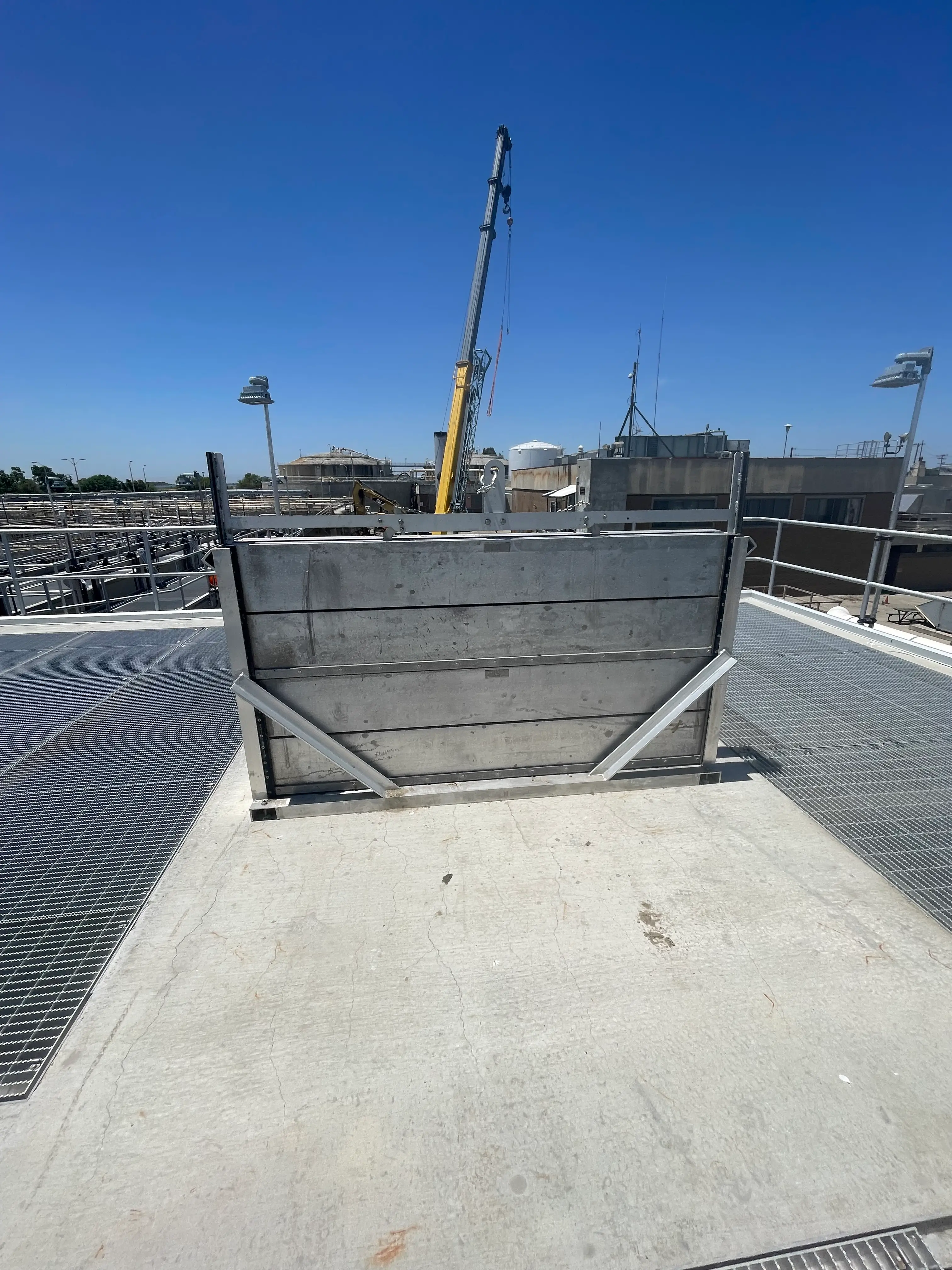
Stop Logs
Stacking, sectional logs used for isolation and level control.
Technical specifications
General
- The stop log assemblies shall be provided as specified herein and as shown in the Contract Documents. Stop logs shall be lowered into place with a lifting device and shall be used to control the flow or water level as required for the application.
Performance Requirements
- Leakage for the stop logs shall be restricted to 0.1 gpm/ft or less of the seal perimeter at the design seating head.
- All of the seals shall be mounted on the log to facilitate seal replacement.
Submittals
- Submittals shall include, at a minimum, detailed custom drawings of the complete stop log assembly and accessories with dimensional and mounting information and a listing of the materials of construction. General arrangement drawings and cut sheets are not considered acceptable drawings.
- Calculations shall be provided to confirm that the deflection is limited to the criteria specified herein.
- A copy of the ISO 9001:2015 certification.
Quality Assurance
- The basis of design for the stop logs is the Model RW3000-S as manufactured by RW Gate Company, Troy, NY.
- All stop log assemblies shall be shop inspected for proper operation prior to shipment.
- Welds shall be performed by welders with ASME Section IX or AWS D1.6 certification.
- The stop log manufacturer shall be ISO 9001:2015 certified.
Materials of Construction
- All stainless steel referenced in this specification shall be Type 304 or Type 304L, ASTM A240 or ASTM A276 unless otherwise indicated herein.
- All welded stainless steel components shall be constructed of Type 304L stainless steel.
- All structural stainless steel used in the construction of stop logs and frames shall have a minimum material thickness of 1/4-inch.
- All non-welded stainless steel components, excluding anchor bolts and assembly bolts, shall be Type 304 stainless steel.
- Anchor bolts and assembly bolts shall be Type 316 stainless steel.
Stop Logs
- The stop logs shall be constructed of formed plate reinforced with stiffeners, as needed, to withstand the specified head conditions. The log shall engage the frame a minimum of 1-1/2-inches on each side.
- The stop log shall be reinforced with plates or channel shaped members to restrict deflection to less than 1/360 of the span or 1/8-inch, whichever is less, at the design head.
- Stop logs shall be designed to ensure that they will not float and they will lower into place through gravity.
- The top of each stop log shall be provided with two slots to receive the lifting device. Lifting hooks and/or pins extending from the stop log are not acceptable.
- All seals shall be mounted on the stop logs.
- Stop logs shall be identical and designed to stack in any sequence.
- Each stop log shall have a tag, constructed of stainless steel, attached via welding, to indicate the manufacturer's name, opening width and maximum head rating as a minimum.
Frame
- The frame shall be constructed of stainless steel plate, formed into "C" shaped channels for rigidity, and shall be reinforced to withstand the specified operating conditions.
- The frame shall be a rigid, one-piece assembly as configured on the Contract Drawings. Frames can be provided in three sections, with bolted corner sections, when shipping restrictions prevent shipping a frame intact.
- The frame shall not contain any rubber or plastic seals or seats.
- Wall mounted frames shall be reinforced with gussets to minimize frame deflection in the unseating head condition.
Seals
- The seal system shall consist of a set of resilient seals along the sides and across the bottom of each log and a UHMWPE wear bar on the side opposite where the seal is mounted.
- The seals and wear bar shall be mounted on the stop logs. No seats, seals or wear bars shall be mounted in or on the frame.
- The seals and wear bars shall be secured with stainless steel assembly bolts. All seals shall be field removable and field replaceable.
Lifting Device
- A stainless steel lifting device shall be provided with stainless steel lifting hooks to install and remove the stop logs from the frame. The chain and shackles shall be of stainless steel construction.
- The lifting device shall be designed to engage each stop log individually for installation or removal from the operating deck.
- The portion of the lifting device that engages the frame shall be outfitted with UHMWPE bearing strips to ensure no metal-to-metal contact occurs between the lifting device and the inside of the frame.
- The lifting device shall be provided with a lifting lug on the top and utilized in conjunction with a hoist or crane.
Storage Racks
- Storage racks shall be provided when shown in the Contract Drawings.
- Storage racks shall provide a storage location for the stop logs when not in use.
- The storage racks shall be constructed of the same material as the stop log frames.
Anchorage
- Anchor bolts shall be 316 stainless steel, fully threaded and shall have a minimum diameter of 1/2-inch.
- Anchor bolts shall be of the epoxy type.
Finish
- All heat tint and slag from the welding process shall be passivated in accordance with ASTM A380. If bead blasting is utilized, the entire frame and the entire stop log shall be bead blasted for a uniform finish.
Installation
- Installation shall be performed in accordance with the stop log manufacturer's installation instructions and the approved installation drawings.
- Installation instructions and installation drawings shall be found in the O&M manual.
- Non-shrink grout shall be applied, by the Contractor, between the frame and the wall to ensure that there is no leakage around the frame.